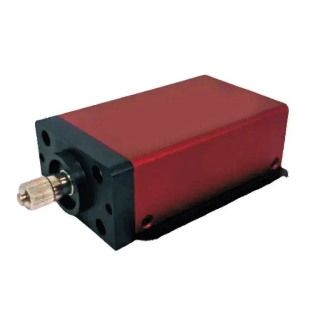


-Operating wavelength:1.0μm to 1.65μm;
-High detection sensitivity(single photon level detection capability);
-Free-running mode(working door width can be adjusted);
-LVTTL/TTL output;
-Can work synchronously inside and outside;
-Key setup parameters are adjustable;
-Free Space Optical/FC Pluggable Optical Interface/Multimode Fiber(62.5um)optional.
| Parameterization | Notation | Test Condition | Minimum Value | Typical Value | Maximum Values | Unit |
| Detector Specifications and Configuration Parameters | ||||||
| Effective pixel diameter | d | – | – | 25 | – | μm |
| operating wavelength | λ | – | 1000 | – | 1650 | μm |
| Output signal amplitude | V\(_{out}\) | – | 2.5 | 3.3 | 5 | V |
| power wastage | PDC | V\(_{IN}\) =5V,T\(_{th}\) =-30℃±5℃ | – | 15.0 | – | W |
| Input Voltage | VIN | – | 12 | – | V | |
| Input Current | I\(_{IN}\) | V\(_{IN}\) =5V,T\(_{th}\) =-30℃±5℃ | – | 1.5 | – | A |
| Operating Temperature | T\(_{A}\) | – | -40 | – | 55 | ℃ |
| weights | W\(_{t}\) | – | – | – | 300 | g |
| Detector Size | S\(_{C}\) | – | 89x62x30 | mm | ||
| Optical performance parameters | ||||||
| photon efficiency | PDE | T\(_{A}\) =25±5℃,T\(_{th}\) =-30℃± 5℃,\(_{T}\) =0.8μs±0.1μs, λ=1550±50nm(InGaAs), λ=1064±10nm(InGaAsP) | 10 | 15 | – | % |
| dark count rate(InGaAs) | DCR (PDE=10%) | – | – | 10 | kHz | |
| dark count rate(InGaAsP) | DCR (PDE=10%) | 5 | kHz | |||
| backpulse probability | APP (PDE=10%) | – | – | 20 | % | |
| 1,T\(_{th}\) :InGaAs avalanche photodiode chip operating temperature. 2,\(_{T}\) :dead time. 3.Ambient temperature for testing the above parameters:TA=25±5℃. | ||||||
| Serial Number | Parameters | Rated Value | ||||||||||||||||||||||
| Parameter setting range | 1 | Detector operating temperature | -30℃~30℃,Minimum step value:0.1℃. | |||||||||||||||||||||
| 2 | Dead Time Adjustment | 0.1μs to 2.0μs,step value:0.025μs. | ||||||||||||||||||||||
| 3 | Avalanche voltage threshold adjustment | 50.0V to 85.0V,step value:0.1V. | ||||||||||||||||||||||
| 4 | Geiger avalanche comparison voltage setting | 0.35V to 1.10V,step value:0.01V. | ||||||||||||||||||||||
| 5 | Detector door width and duty cycle adjustment | Working gate width:≥0.1us,working period:>0.1us;step value:0.01us. | ||||||||||||||||||||||
| Serial Number | Parameters | Rated Value | ||||||||||||||||||||||
| Recommendation working Conditions | 1 | Detector operating temperature | -30℃~0℃ | |||||||||||||||||||||
| 2 | dead time value | 0.80μs | ||||||||||||||||||||||
| 3 | Avalanche voltage threshold adjustment | See test report for details | ||||||||||||||||||||||
| 4 | Geiger avalanche comparison voltage setting | 0.45V to 0.90V | ||||||||||||||||||||||
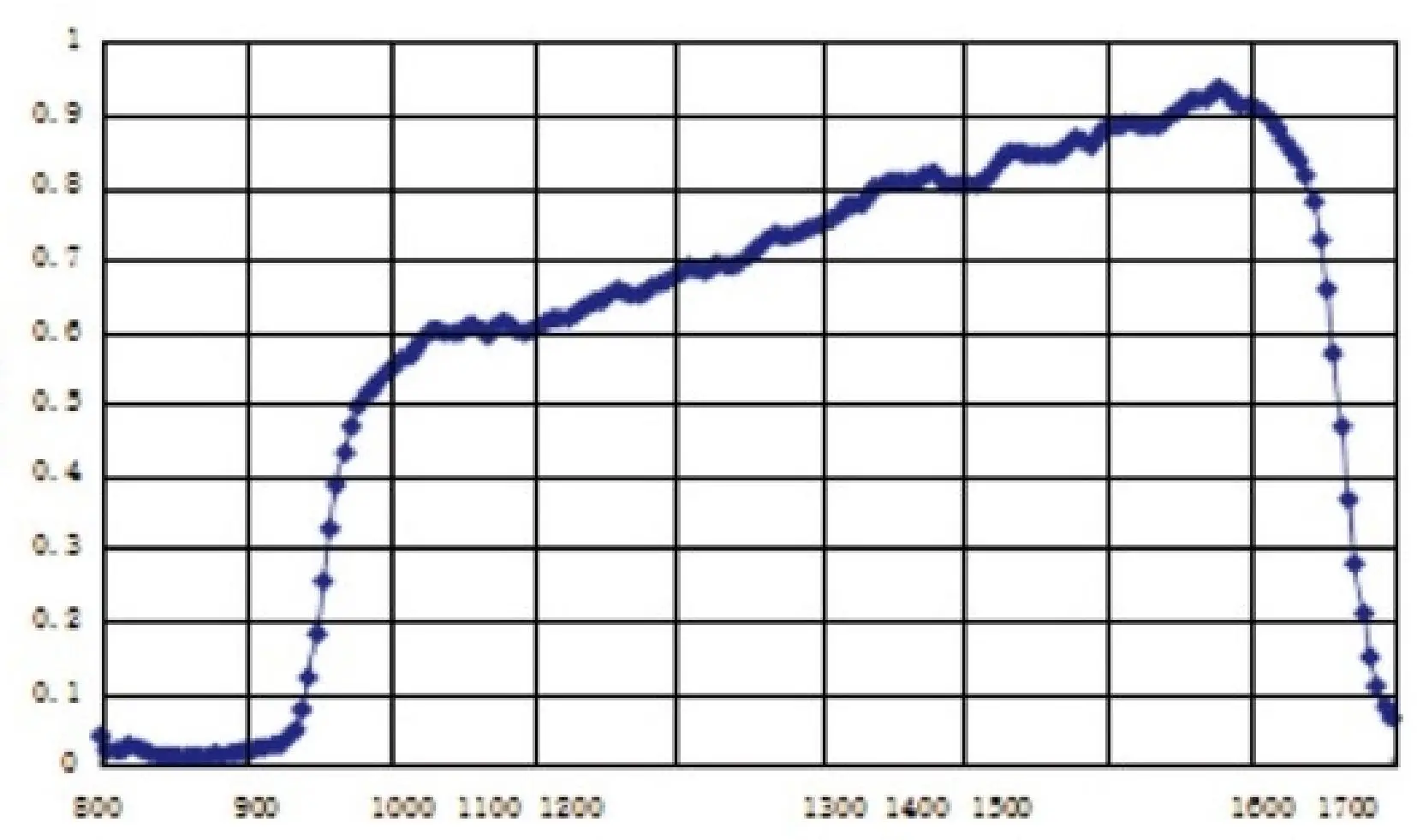
wawelength
Fig.1 InGaAs spectral response characteristic curve
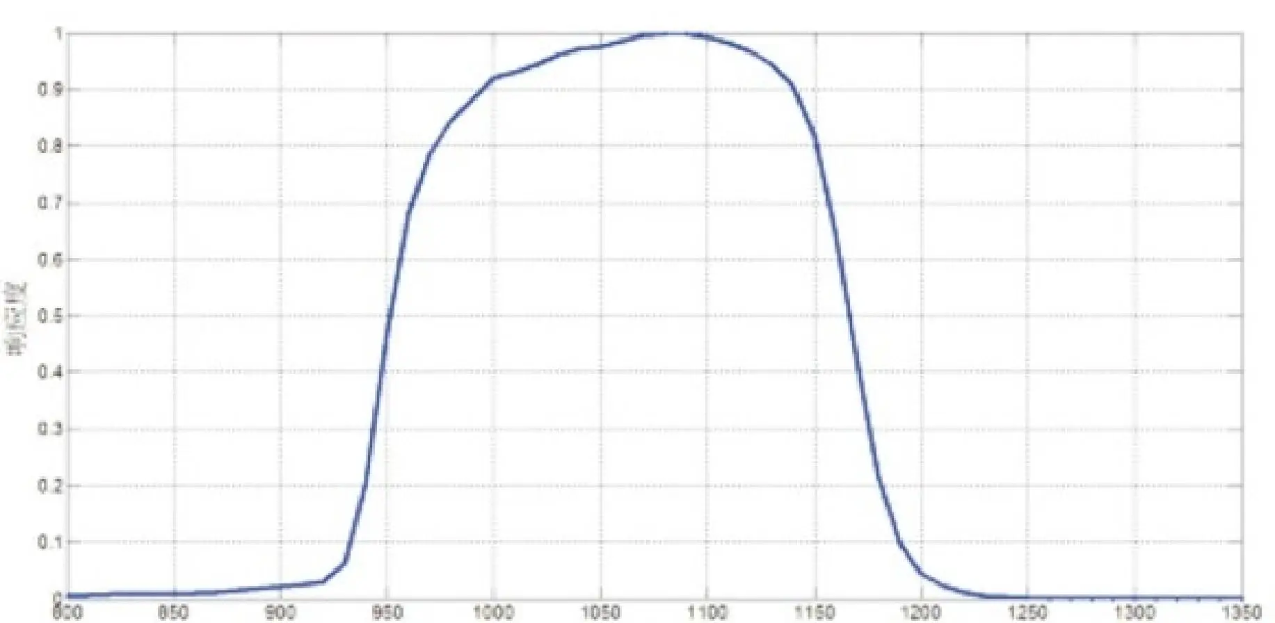
V
Fig.2 InGaAsP spectral response characteristic curve
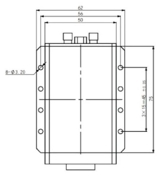
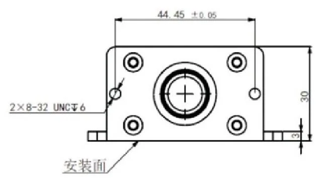
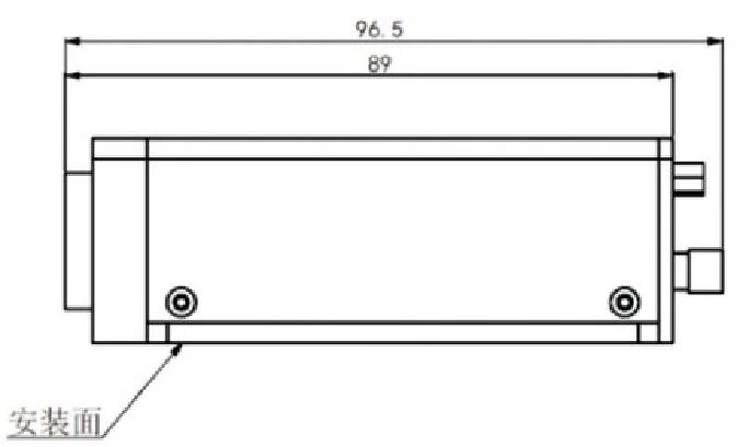
Figure 3 Product form factor
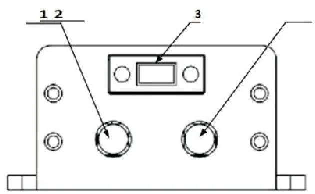
Figure 4 Electrical connector arrangement and numbering
| Electrical Connector Number | Electrical Connector Type | Functionality |
| 1 | SSA-K | Synchronized signal input port |
| 2 | J30J-9TJW-J | Power supply and UART port |
| 3 | SMA-K | Avalanche signal output port |
| J30J-9TJW-J The numbering of each port is shown in Figure 5. | ||

Figure 6 J30J-9TJW-J Port Numbers and Their Locations (Bottom View)
| Notation | Functionality | Port Numbering Horn (wind Instrument) | Notation | Functionality |
| UART TX | UART output port | 6 | GND | grounding port |
| UART TX | UARTinput port | 7 | GND | grounding port |
| GND | UART ground port | 8 | POWER 12.0V | Positive Input Port |
| GND | ground port | 9 | POWER 12.0V | Positive Input Port |
| GND | ground port | – | – | – |
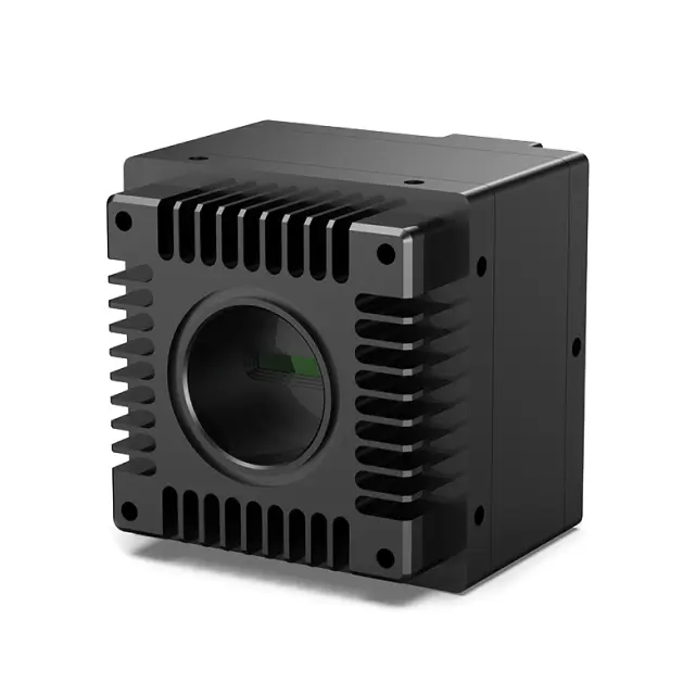
Visible Light⁺ Near-Infrared Camera
This camera is suitable for the spectral range of 400-1700nm, covering the visible light to shortwave
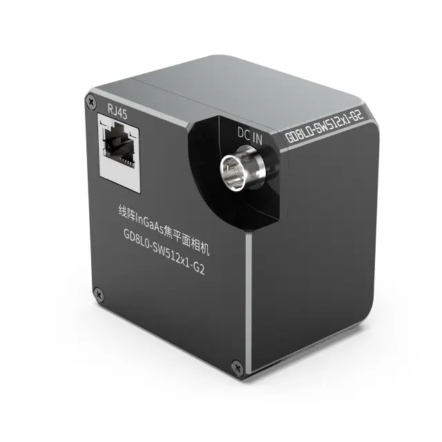
InGaAs Linear Focal Plane Camera
The industrial grade linear array shortwave infrared camera is designed for the spectral ange of 900-1700nm
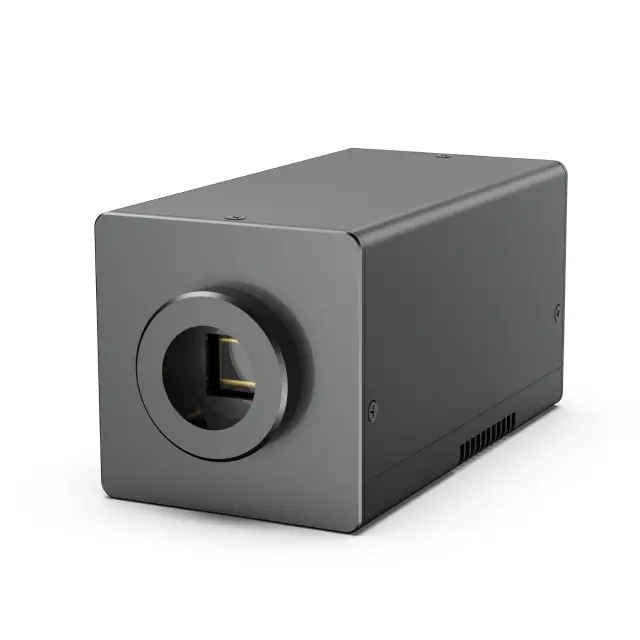
InGaAs Face Array Focal Plane Camera
This product uses domestically produced high sensitivity InGaAs array detectors, with array sizes of 320×256
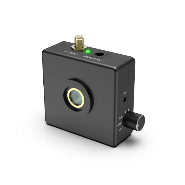
InGaAs Avalanche Photon Detector
This product is a compact near-infrared avalanche photodetector with a core circuit made of domestically
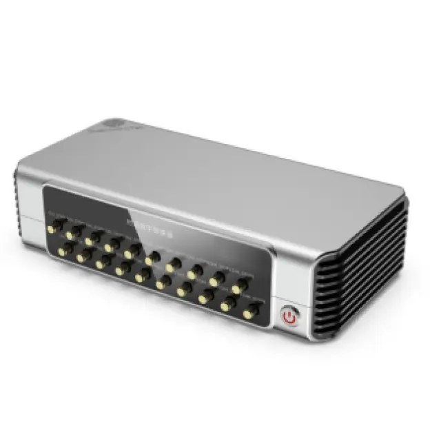
Time-to-Digital Converter
The QTDC-16CH-0A is a compact, high-precision measurement instrument featuring 16 acquisition
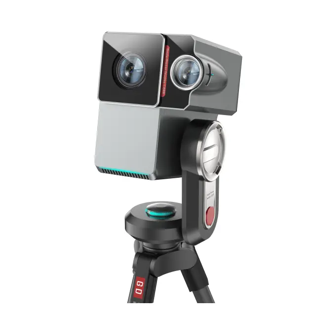
Single Photon Ranging System
This product adopts a fiber optic coaxial optical path design and an integrated system design,which has good stability