


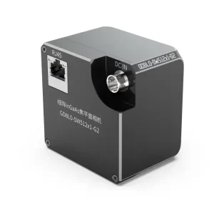
Line Scan Cameras
As the name suggests, a line scan camera captures images in a linear format, with its sensor arranged in a single line.
An area scan camera with a resolution of 640×480 means it has 640 pixels horizontally and 480 pixels vertically.
A line scan camera, however, defines its resolution by the horizontal pixel count. For instance, a 2048-pixel line scan camera has 2048 pixels horizontally and typically only 1 pixel vertically (except for RGB cameras and TDI cameras).
Evolution of Line Scan Sensors
1970s: Most line scan sensors used MOS (Metal-Oxide-Semiconductor) technology.
Late 1970s: CCD (Charge-Coupled Device) sensors began to develop rapidly and have remained dominant to this day.
Mid-1980s: CMOS (Complementary Metal-Oxide-Semiconductor) sensors emerged.
Historically, CCDs had slower imaging speeds compared to CMOS, and CMOS sensors were more expensive than CCDs until 2010.
Post-2010: Major camera manufacturers shifted focus to CMOS development, leading to widespread practical adoption.
CMOS sensors are expected to dominate future line scan cameras, with the key trade-offs between CCD and CMOS lying in imaging speed and sensitivity.
Several key parameters of line-scan cameras:
Resolution: The total number of pixels on the sensor, indicating the horizontal imaging resolution.
Maximum Data Rate: The highest amount of data the camera can process per second.
Line Rate: The maximum number of image lines the camera can capture per second. For example, for a camera with a resolution of 8192×1 pixels and a data rate of 160 MHz, the line rate can be calculated as 160M/8192 ≈ 19000 lines/second. This means the camera captures up to 19000 lines per second, producing an image with a resolution of 8192 pixels horizontally and 19000 pixels vertically, resulting in an approximate image size of 160 MB per second.
Pixel Size and Lens Dimensions: CCD sensors typically have a minimum pixel size of 5 μm, as further miniaturization negatively affects sensitivity and manufacturability. CMOS sensors, however, can achieve pixel sizes nearly half as small as CCDs.
The choice of camera is crucial and has a significant impact on the overall system cost. High-resolution cameras require larger lenses, higher data transmission rates demand faster cables, and larger data volumes necessitate more powerful processing cards and computing systems.
Modern CCD cameras, limited by image acquisition speed, often utilize multi-tap configurations. Each tap generally processes up to 40–60M of data. For example, a 160M camera may employ 4 taps, each operating at 40M, with a total rate of 40M × 4 = 160 MHz. Tap configurations may vary, including single-tap (1), dual-tap (2), triple-tap (3), and octal-tap (8). Currently, CCD speeds are capped at 400M, whereas CMOS sensors can achieve speeds of up to 1.6 GHz, with further advancements expected.
Output formats of cameras include 8-bit, 10-bit, and 12-bit configurations. Depending on the design, outputs may be single-channel (pixels are sequentially output as 1, 2, 3, …, 8192) or multi-channel, where pixels are split across channels (e.g., odd pixels in one channel and even pixels in another). However, default configurations are typically sufficient for most applications.
The primary interfaces for line-scan cameras are GiGe and Camera Link, with high-speed cameras relying on HS Link.
Key camera settings include:
Exposure: This parameter directly affects the line rate and must be set below the maximum achievable rate. For instance, for a camera with a line rate of 19000 lines/sec, the exposure time should be set to approximately 1 sec / 19000 ≈ 53 μs. Accounting for delays, the practical value is around 47 μs to achieve maximum performance. A shorter exposure results in darker images, while longer exposure increases brightness.
Gain/Offset: Adjustments to grayscale levels of captured images. While useful in low-light conditions, excessive adjustments (beyond 20% of the default value) can reduce image clarity and negatively impact subsequent analysis.
Other settings, such as image averaging or offset calibration, can be found in the camera manual.
Application Fields
Line-scan cameras are widely used in continuous production environments, such as steel metallurgy, non-ferrous metals, electronic materials, textiles, paper manufacturing, and LCD inspection. While area-scan cameras can serve similar purposes, line-scan cameras are often more suitable for high-speed applications, albeit at higher costs.
Several Important Parameters of Line Scan Cameras:
Resolution: The number of pixels, i.e., how many pixels are on the sensor.
MAX DATA RATE: This refers to the maximum amount of data the camera can acquire per second.
Line Rate: This refers to the maximum number of image lines the camera can acquire per second.
For example, with a resolution of 8192*1 and a data rate of 160 MHz, the camera’s line frequency is calculated as 160M / 8192 = 19,000 lines per second. This means the camera can capture 19,000 lines per second, with a horizontal resolution of 8192 pixels and a vertical resolution of 19,000 pixels. The size of the image captured in one second is approximately 160 MB.
Other factors include the pixel size and lens size. Typically, the smallest pixel size for CCDs is 5µm; anything smaller is difficult to produce and also results in poor sensitivity. CMOS pixels can be nearly half the size of CCD pixels.
The selection of the camera is crucial, as it directly impacts the overall equipment cost. If the pixel count is high, larger lenses must be used. For large data volumes, high-speed data cables are needed, and image processing cards are also necessary. High data volumes also require higher computational power, which places higher demands on the computer.
Taking mainstream CCD cameras as an example, since the camera’s image acquisition speed is limited, each tap can typically acquire a maximum of 60 MB of data. Therefore, current cameras usually use a multi-tap processing method. For instance, in a 160 MB camera, there are four taps, each with 40 MB of image capture. This results in 40 MB * 4 = 160 MHz. There are also single-tap (1), dual-tap (2), triple-tap (3), and octal-tap (8) configurations. Currently, CCD image acquisition speeds are below 400 MHz, while CMOS can reach up to 1.6 GHz (and may go higher in the future).
The camera output modes also vary, including 8-bit, 10-bit, and 12-bit outputs. There can be single output, where images are taken in sequence (1, 2, 3, ~8192), or dual output (1, 3, 5, 7 / 2, 4, 6, 8), and other configurations like (1, 3, 5 ~ 4095 / 4097, 4099 ~ 8191). The output mode can be roughly understood here (using default values typically does not affect image acquisition).
The main interfaces for line scan cameras are still GigE and CameraLink, while high-speed cameras require HSlink.
Some key camera settings include Exposure, Gain, and Internal/External Trigger Mode. There are many other less commonly used settings, such as Average Image Intensity, Offset Adjustment, etc.
Exposure: This setting is directly related to the camera’s line frequency and must be lower than the maximum line frequency that can be captured. For example, for a camera with a 19,000 line frequency, to capture 19,000 lines, the setting would be 1 sec / 19,000 = 53 µs. Some delays are also involved, so a setting around 47 µs is required to achieve the maximum line frequency. (The lower the value, the darker the captured image; the higher the value, the brighter the image.)
Gain/Offset: This adjusts the grayscale of the captured image. It can be used when the illumination is insufficient, but excessive use will decrease image clarity and affect analysis. It is not recommended to use gain/offset adjustments, and even if used, they should not exceed 20% of the default value.
Other settings can be found in the camera’s manual.
Applications of Line Scan Cameras:
Line scan cameras are primarily used in continuous production lines (web applications), such as in steel metallurgy, non-ferrous metals, electronic materials, textiles, papermaking, LCD production, etc. In fact, any application where area scan cameras are used can also be performed by line scan cameras, but the difference is the cost.
Surface Defect Detection Equipment for Electronic Copper Foil:
The electronic copper foil has a width of 450mm, with a production line speed of 120 meters per minute, and the smallest defect to be detected is 0.2mm.
When selecting equipment, a 4096-pixel line scan camera can be considered. Using a regular F-mount lens, the horizontal resolution is about 0.11mm, which can detect defects as small as 0.2mm.
Now, how do we choose the vertical resolution?
The production line speed is 120 meters per minute, which equals 2 meters per second, or 2000mm per second.
If we want to maintain consistent horizontal and vertical resolution, the vertical resolution should be 2000mm / 0.11mm = 18,180 lines. The camera needs to capture 18,180 lines per second to complete the full-width imaging of the product. Therefore, we can choose a 4096-pixel camera with a line frequency of 19,000 lines per second. This type of camera can capture the full-width image of the product.
But will the camera scan the same line multiple times in one second?
Using an external trigger will prevent this issue.
An external trigger means that an external pulse is sent to the camera, which then scans one line. The scanning frequency is determined by the speed of the production line: faster line speed results in a higher scanning frequency, and vice versa.
External triggers are typically implemented using an encoder. There are two main types of encoders: one that sends a fixed pulse for every fixed distance (e.g., 1mm per pulse), and another that sends a fixed pulse for every full rotation. The encoder output signal can come in different forms, such as LineDriver, and the camera can receive different signal types, including TTL, LVDS, differential, etc.
Let’s use the example of electronic copper foil again. If we use a fixed pulse encoder where 1 pulse occurs every 1mm, this means the camera will scan and take an image every 1mm. In this case, the horizontal resolution is 0.11mm, and the vertical resolution will be 1mm. This could cause image distortion. There are two solutions:
When selecting the encoder, choose one that matches the camera’s line frequency.
Adjust the camera settings to change the line frequency.
All cameras include a convert mode, which converts the pulse received into the required value. If you want both the horizontal and vertical resolutions to be 0.11mm, you can increase the value by 9 times. The camera will automatically scan 9 times for each pulse received, so each line’s resolution will be 1mm / 9 = 0.11mm. This will make the horizontal and vertical resolutions consistent.
For example, with 1 pulse every 1mm, if the camera scans 9 lines for each pulse:
When the production line speed is 1 meter per second, the camera scans 9000 lines per second (1000mm / 1 * 9 = 9000 lines per second). For every meter of production line movement, the encoder generates 1000 pulses, and the camera captures 9000 lines.
When the production line speed is 2 meters per second, the camera scans 18,000 lines per second (2000mm / 1 * 9 = 18,000 lines per second). For every 2 meters of production line movement, the encoder generates 2000 pulses, and the camera captures 18,000 lines.
As long as the external trigger is properly set up, the camera will not scan the same line repeatedly.
Now, this also brings us to color cameras. Color cameras use three lines, scanning the same line in parallel to combine the color image for that line.
There are also TDI (Time Delay Integration) cameras, with models like 8-line, 16-line, and even 32-line, with the highest reaching 512 lines. These cameras capture images from the same line to get the best image quality. They are more expensive, have lower lighting requirements, but require a very high data rate.
Selection of Line Scan Camera, Lens, and Light Source:
With the widespread adoption of machine vision and the improvement in industrial production line speed and precision, line scan systems are becoming increasingly recognized by vision engineers and end users.
Line scan systems are used in scenarios where there is relative motion between the object under test and the camera. By using a line scan camera to capture data at high speed, each time one line is captured, the system moves to the next unit length, continuing to capture the next line. Over time, this process assembles a two-dimensional image, similar to the image captured by a flat-panel camera. The difference is that the height of the image can be infinitely long. Software is then used to crop this “infinitely long” image into a specific height and process it in real-time or save it in memory for later processing.
The vision system consists of the line scan camera, lens, light source, image acquisition card, and vision software.
The motion control system includes the motor, motor driver, motion control card or PLC. To ensure synchronization between the captured image and the conveyor belt, an encoder is often needed.
Since the amount of data captured by a line scan camera is large, a high-performance industrial computer is required, with large memory and storage capacity. The motherboard should provide PCI, PCI-E, or PCI-X slots.
Generally, the configuration and selection process for a flat-panel vision system follows this order:
Camera + Acquisition Card -> Lens -> Light Source
For line scan projects, the process is similar. Based on the system’s detection accuracy and speed requirements, the resolution and scan speed of the line scan CCD camera are determined, along with the corresponding acquisition card. When selecting the lens for the line scan camera, the lens mount (interface) must also be considered, followed by the final selection of the light source.
Selection of Line Scan Cameras (Industrial Line Scan Cameras)
Calculating Resolution:
Divide the width by the minimum detection precision to obtain the required pixels per line.
Selecting the Camera:
Divide the width by the pixel count to determine the actual detection precision.
Divide the moving speed per second by the precision to get the number of scan lines per second.
Based on these values, select the appropriate camera.
Example:
Width: 1600 mm
Precision: 1 mm
Motion speed: 22000 mm/s
Calculation:
Required pixels: 1600/1=16001600 / 1 = 1600 pixels
Minimum selection: 2000 pixels (choose a 2K camera)
Actual precision: 1600/2048=0.81600 / 2048 = 0.8 mm
Required scan speed: 22000 mm/0.8 mm=27.5 kHz
Chosen camera: 2048 pixels at 28 kHz
Selection of Line Scan Lenses
Why should the lens be considered when selecting a camera? Common line scan camera resolutions include 1K, 2K, 4K, 6K, 7K, 8K, and 12K, with pixel sizes such as 5 µm, 7 µm, 10 µm, and 14 µm. The sensor size thus ranges from 10.24 mm (1K × 10 µm) to 86.016 mm (12K × 7 µm).
Clearly, the C-mount interface cannot meet these requirements, as it supports a maximum chip size of 22 mm (approximately 1.3 inches). Many cameras use interfaces such as F, M42×1, and M72×0.75. Different lens interfaces correspond to different flange distances, which determine the working distance of the lens.
Optical Magnification (β, Magnification):
Once the camera resolution and pixel size are determined, the sensor size can be calculated. Dividing the sensor size by the field of view (FOV) gives the optical
magnification:
β=Sensor Size/FOV\beta = \text{Sensor Size} / \text{FOV}
Interface (Mount):
Common interfaces include C, M42×1, F, T2, Leica, and M72×0.75. Once the interface is determined, the corresponding length can be calculated..
Flange Distance:
Flange distance refers to the distance from the camera interface plane to the sensor and is a crucial parameter. It is determined by the camera manufacturer based on their optical path design. Cameras with the same interface may have different flange distances depending on the manufacturer.
With the optical magnification, interface, and flange distance known, the working distance and adapter ring length can be calculated.
MTF (Modulation Transfer Function):
After selecting these parameters, an essential step is ensuring the MTF (Modulation Transfer Function) value is adequate. Many vision engineers are unaware of MTF, but for high-end lenses, MTF is critical to evaluating optical quality.
MTF encompasses details about contrast, resolution, spatial frequency, chromatic aberration, and more. It provides a detailed representation of the optical quality at various points, including the center and edges of the lens.
Even if the working distance and field of view meet the requirements, if the edge contrast is insufficient, it is necessary to reconsider whether to choose a higher-resolution lens.
Selection of Line Scan Linear Light Sources
In line scan applications, commonly used light sources include LED lights, halogen lamps (fiber optic light sources), and high-frequency fluorescent lamps.
Halogen Lamps
Halogen lamps, also known as fiber optic light sources, are characterized by their exceptionally high brightness. However, they have a notable drawback: a short lifespan of only about 1,000–2,000 hours, necessitating frequent bulb replacements. The light source is a halogen bulb, which emits light through a specialized optical lens and light distribution system, then transmits it via optical fibers. The light source has high power, reaching up to 250 watts. Halogen lamps are also referred to as cold light sources because the light emitted from the fiber optic output is not hot and maintains stable color temperature. This makes them suitable for environments sensitive to temperature changes, such as illumination for coordinate measuring machines (CMMs). For line scanning applications, halogen lamps are often equipped with glass focusing lenses at the output to further concentrate and enhance brightness. For longer linear light sources, multiple halogen light sources are used together to illuminate a single optical fiber.
High-Frequency Fluorescent Lamps
The emission principle of high-frequency fluorescent lamps is similar to that of regular fluorescent lamps, but the tubes are industrial-grade products. They are ideal for large-area illumination, offering high brightness and low cost. However, the primary disadvantages of fluorescent lamps are flickering and rapid attenuation. High-frequency power supplies are essential for fluorescent lamps, ensuring that the flicker frequency is much higher than the image capture frequency of the camera (or the line scanning frequency for line scan cameras) to eliminate image flickering. Specialized high-frequency power supplies can achieve frequencies as high as 60 kHz.
LED Light Sources
LED light sources are currently the mainstream choice for machine vision applications, offering the following features:
DC Power Supply with No Flicker: LED lights operate without flickering, ensuring image stability.
Long Lifespan: Professional-grade LED lights can last up to 50,000 hours, maintaining at least 50% of their brightness.
High Brightness: The brightness of LED light sources is comparable to that of halogen lamps and continues to improve with advancements in LED technology (e.g., some American AI LED light sources achieve up to 90,000 lux).
Flexible Designs: LED light sources can be designed in various structures, such as direct illumination, collimated light with focusing lenses, backlight, coaxial lighting, and diffuse dome-shaped lighting.
Multiple Color Options: Available in red, green, blue, white, as well as infrared and ultraviolet. Different colors, or wavelengths, can be selected to suit the surface characteristics and material properties of the object being inspected, achieving optimal imaging results.
Angle Analysis Between Line Scan Cameras, Light Sources, and Test Objects
Taking glass inspection as an example, the defects to be inspected include dirt, stones, impurities, bubbles, scratches, cracks, and damages. These defects can generally be classified into two categories: those on the surface of the glass and those within the glass. Different defects exhibit varying gray levels in the image—some appear black, some white, and others gray. Moreover, the contrast of defects changes with different illumination angles or camera receiving angles. For instance, at a particular angle, one type of defect might have the highest contrast, while other defects may be less visible or even completely undetectable. Therefore, extensive analysis and combinations are required to determine the optimal light source selection and the relative angles among the camera, light source, and test object.
Adjustment of Light Sources and Lenses
In a line scan system, the effective working area for both the light source and the camera is a narrow strip. This means that the light source’s brightest narrow strip must align perfectly parallel to the camera’s sensor; otherwise, only a single bright point at the intersection will be captured. Hence, mechanical installation and adjustment can be labor-intensive. Additionally, due to the relatively wide field of view, line light sources have two special requirements: uniformity and linearity. Variations in brightness across different positions of the line light source directly affect the image’s brightness, making LED light sources easier to control than halogen lamps in this regard. The linearity of the emitted light depends on the consistency of the LED’s emission angles, the linearity of the collimating lens, and the linearity of the line light source housing.
Given the complexity of onsite environments, it is often tempting to spend more time on onsite adjustments. However, as mentioned earlier, the relative angles among the camera, light source, and test object significantly influence detection results. Therefore, we recommend conducting laboratory tests first to develop a plan, followed by onsite adjustments. This approach ensures higher confidence and improves adjustment efficiency.
Line Scan System Components and Resolution Matching
Apart from mechanical structures, the main components of a line scan system include machine vision and motion control.
To ensure that the captured images are neither stretched nor compressed, one essential rule must be followed: “The horizontal and vertical resolutions must be equal.”
Define the following variables:
Hc: The number of pixels per line in the line scan camera (unit: pixel)
Lo: The width of the target object (unit: m)
Vo: The running speed of the target object (unit: m/s)
Vc: The line scan rate of the line scan camera (unit: Hz, i.e., lines per second)
To: The time for the target object to pass during the scan of one frame (unit: s)
Tc: The time for the line scan camera to scan one frame (unit: s)
Horizontal Resolution:
Horizontal Resolution = (L₀)/(Hc) Vertical Resolution: Vertical Resolution = (VₒTₒ)/(VcTc)
Since Tₒ = Tc, the following principle applies:
(Lₒ)/(Hc) = (Vₒ)/(Vc)
Thus, the line scan rate of the camera is given by:
Vc = (Hc · Vₒ)/(Lₒ)
Conclusion
Line scan cameras play an essential role in modern industrial imaging systems, offering unparalleled precision and efficiency in high-speed production environments. From advancements in CCD and CMOS technologies to the careful selection of lenses, light sources, and other system components, the success of line scan applications depends on a holistic understanding of their technical parameters and operational requirements. Proper alignment of components, rigorous pre-installation testing, and adherence to resolution matching rules ensure optimal performance and reliability. As technology continues to advance, line scan cameras will remain indispensable tools for industries requiring high-speed, high-resolution imaging solutions.