Home » Support
Home » Support
We offer customized optical components, optical systems, and optical modules based on customer requirements, including specific optical parameters, spectral characteristics, and structural design.
We provide custom electronic components, circuit board designs, and microelectronic assemblies according to the customer’s technical specifications and functional requirements to meet personalized electronic product needs.
Using CAD software for mechanical design and structural optimization, we customize various mechanical parts and precision structures to ensure the product design meets the customer’s engineering requirements.
We offer creative and aesthetic appearance design services, including 3D modeling, rendering, and visual effect design, to meet the customer’s market demands and user experience requirements.
By integrating theories of fiber optics, applied optics, optical materials, and manufacturing and utilizing computer simulation software such as Zemax, Code V, and LightTools, we simulate, analyze, and optimize optical systems.
The ability to achieve circuit design through the use of analog circuit design, digital circuit design, PCB layout, component selection, and signal integrity simulation.
Applying knowledge from disciplines such as mechanical engineering, materials science, and mechanics, we utilize techniques like sketching, 3D modeling, and engineering drafting to complete spatial structural designs of products, ensuring manufacturability and assembly feasibility.
By means of hand drawn design, 3D modeling, and rendering product renderings, creative, aesthetic, and industrial practicality design of product appearance is carried out based on three-dimensional spatial modeling art.
Using Zemax computer simulation software, basic data such as the types, geometric shapes, and optical parameters of optical components are analyzed and optimized through the creation of mathematical models to simulate parameters such as light transmission and light field distribution. Performance indicators such as transmittance, loss, and beam quality of the optical system are obtained, improving the design capability and efficiency of the optical system.
Using HFSS software, evaluate attenuation (S21), reflection (S11), and coupling effects at different frequencies through frequency domain simulation analysis. Analyze signal transmission delay, jitter, and bandwidth parameters through time domain simulation to evaluate the impact of different design schemes, materials, and layouts on signal integrity, in order to optimize design and improve product performance.
The ability to achieve radio frequency simulation through the use of radio frequency electromagnetic field calculation, antenna design, power amplifier design, microwave network analysis, modulation and demodulation technology, and bit error rate analysis.
Based on the knowledge of materials, thermodynamics, mechanics and other disciplines, using Ansys finite element analysis software, the temperature field and stress field of optoelectronic hybrid integrated products are simulated and analyzed, in order to accurately calculate the temperature distribution, temperature rise, stress deformation and other data indicators during product operation, and improve the reliability and efficiency of device design.
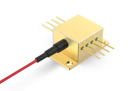
Encapsulating multiple optical components in a small structure to achieve highly integrated and efficient optical transmission and processing results in a smaller and lighter integrated packaging technology for optical components.
At present, it can complete the coupling of single channel and high-density (spacing127um) array (>8 channels) tapered fiber, single-models fiber (core diameter 9um), optical quantum chip (spacing 150um, spot 3.5um), microlens, etc.
Pressing and soldering extremely fine metal wires with good ductility and conductivity onto the surface of substrate-substrate, substrate-chip, or chip-chip to achieve mutual correlation of electrical characteristics is a commonly used process in multi-chip microassembly. At present, it is able to accurately complete spherical and wedge-shaped bonding of various welding wires.
Gold Wire: 15um – 75um
Aluminum Wire: 18um – 75um
Gold Belt: 50um x 12.5um – 100um x 25.4um
The flip chip process refers to the direct deposition on the l/O pads of a chip, or after RDL wiring, deposit bumps are made, and then the chip is flipped for heating to combine the melted solder with the substrate or frame, with the electrical side of the chip facing downwards.
It can accurately complete the installation of various inverted chips and ordinary chips and can handle a minimum chip size of 0.25mm.
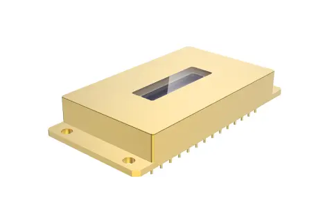
It is a type of resistance welding that uses two roller electrodes to contact the metal cover plate to form a closed circuit. A large amount of heat is generated at the high resistance point through pulse current,causing the cover plate to be in contact with the tube seat. The contact point of the rod ring is in a molten state, and after solidification, a series of welding points are formed, and the welding points overlap with each other, forming an airtight weld seam, achieving the purpose of sealing. Capable of completing pipe shell welding products with dimensions of 4*4mm and above, with air tightness meeting aerospace grade standards of 5*10⁻⁹ (Pa·m3 )/s.